You must be signed in to read the rest of this article.
Registration on CDEWorld is free. Sign up today!
Forgot your password? Click Here!
Since the 1970s, the number of certified dental laboratory training programs in the United States has plummeted.1 The number of military programs that trained dental laboratory technicians also have been reduced severely, and the remaining population of dental technicians is aging.2 By one recent estimate, if the number of dental technicians continues to decrease at its current pace, by 2023, fewer than 9,000 technicians will be working in the United States.3 Given the dearth of talented and well-trained personnel, the dental laboratory industry has been struggling to meet the needs of the growing number of adults who need full dentures. That amount is projected to reach 37.9 million by 2020.4
Adding to the issue is that some dentists have become less willing to provide patients with removable dentures. They may worry about achieving predictable outcomes,5 a concern that is compounded by the fact that some patients seeking dentures may have unreasonable expectations.6,7 The traditional processes for fabricating removable dentures are notoriously time consuming and error prone.8 Many dentists also have been discouraged by declining financial returns, given the overhead costs and extensive chairtime.
A new technology that makes it easier and more predictable for the general dental practitioner to deliver removable dentures may reverse this situation. Computer-aided design/computer-aided manufacturing (CAD/CAM) and rapid prototyping tools that, for decades, have been revolutionizing dentistry9-12 recently have been applied to denture fabrication, enabling the creation of so-called “digital dentures.”13 Such products make it possible to produce extremely accurate dentures twice as fast as when using conventional analog processes. Typically only three office visits are required, instead of the five or more as required with the traditional denture process; each visit with the digital process often requires less than 45 minutes of chairtime. Four commercial entities have entered the marketplace, including Pala Digital Dentures (Heraeus Kulzer); AvaDent Digital Dentures (Global Dental Science); DENTCA CAD/CAM Denture (DENTCA, Inc); and Denture Design™ (3Shape).
Key Steps in Making a Digital Denture
The first step in making a digital denture is to capture high-quality impressions of the edentulous arch or arches, the vertical dimension of occlusion, and the jaw relation. This can be accomplished in a single appointment using specially developed impression trays equipped with a slot assembly that supports a Gothic-arch tracing device, a well-established method for obtaining centric relation (CR) bite records.14,15 The starter kit from one manufacturer includes four sizes of impression trays, all of which have been designed with intentionally short peripheral borders. This is based on the work of Dr. Joseph Massad, who years earlier developed edentulous impression trays for denture patients that were intentionally 3 mm to 4 mm short of an average peripheral border.16 This was in response to problems that dental laboratories were experiencing with impressions that were underextended in the posterior maxilla and overextended elsewhere. Typically, a significant amount of clinical adjustment by an expert dental technician is required to complete dentures from such records. The kit also includes bite plates for single-arch cases to help accomplish Gothic-arch tracing, a vertical dimension measuring tool, tracing paper to be applied to the Gothic-arch tracing plate, and complete clinical support documentation. The impression materials included in the kit are heavy-body and light-body scannable polyvinyl siloxane, which has been documented to provide superior performance.17-19
The first step in making an impression is to select proper tray size. This can best be accomplished by matching the borders of the tray to the borders of the denture; the denture should not be placed inside the tray, as this will lead to selection of a bigger tray size than needed. If no existing denture is available, the tray should be tried into the oral cavity. Confirmation that the tray extends into the vestibule and the area of the hamular notches, which is optimal, can be facilitated by placing photographic cheek retractors into the patient’s mouth and using them to retract the buccal soft tissues. The authors have found that the medium tray of one system fits approximately 80% of patients.
An impression border that looks too thick indicates that the tray selected was too large. Conversely, a significant amount of show-through on the tray or incomplete coverage of the palatal area suggests that it was too small. In general, use of a smaller tray tends to be better than a larger one. The goal is to achieve as close to the actual fit of the ridges as possible, leaving just enough room for a uniform thickness of impression material.
The thermoplastic tray material allows for minor adjustments using either heat or a lab bur to remove excess material. Different sized trays can be used in the same patient’s maxilla and mandible. Each arch should always be evaluated independently. (The pins are not interchangeable.) The trays lack handles to keep from distorting the impression; however, the trays incorporate finger rests to facilitate use.
Once the bite, mandibular, and maxillary impressions have been obtained, they are sent to the dental laboratory, digitized using a scanner, and articulated to the bite using automatic impression-recognition software. All digital denture technologies incorporate some version of orthodontic software that allows for recording and movement of teeth based on the needs for occlusion and esthetics. The Pala process uses 26 anatomic landmarks to determine tooth positions. This eliminates the need to mark a midline or determine incisal-edge position or lip support. Instead, by using the anthropometric averages, the teeth can be positioned based on the patient’s anatomy.
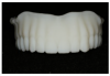
When the design has been completed, the data are sent to a 3D printer, and white resin prototypes are fabricated, reproducing the requirements for midline, occlusion, and other aspects. Extraordinary accuracy can be achieved because an ideal impression with proper border molding has been obtained, and the 3D printer produces the prototype with zero distortion.
At the second patient visit, the prototype is tried in. With traditional removable dentures, the base plates typically never are sufficiently retentive, so glue and denture adhesive must be used to accurately evaluate the tooth position. In the digital denture try-in phase, however, that problem is eliminated. The try-in typically has good suction and is border molded well. It covers the denture base as it should, so tooth position, occlusal contacts, and smile line can be evaluated. The patient is asked to do phonetic trials; freeway space, overbite, and overjet can all be checked. The patient can scrutinize the mold of the anterior teeth and decide whether the impressions are big enough and whether the teeth are too square or too round. If any corrections are required, the clinician can draw on the prototype, and the software can be adjusted to accommodate the corrections.
Case Report
A 73-year-old woman wanted to replace her upper denture. Though it was worn, the patient was satisfied with the fit, retention, and arch form. In the mandible, the patient had natural teeth and an implant-borne removable partial denture.
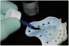
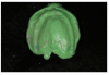
At the first appointment, a large Pala Digital Denture tray was determined to be slightly smaller than the existing denture. However, when tried in the mouth, the clinician could detect no impingement on the soft tissue. Denture adhesive was applied to both the internal surface and the borders of the denture tray to ensure that during border molding, the material would adhere properly to the tray (Figure 1), as well as to the bite plate for the lower arch. The authors believe that the use of the Pala system’s adhesive is essential, as it provides control over the normal shrinkage of the polymer component in the impression material and its relationship to the tray, helping to ensure an optimal fit.
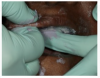
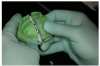
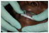
The heavy-body impression material was then injected into the tray to cover the entire surface—palatal, vestibular, and vertical, up to and including the tray borders—and the tray was seated in the mouth. The photographic cheek retractors were removed, and a finger was positioned in the finger rest to help seat the tray evenly and hold it in place (Figure 2) while doing some border molding, moving the lip and frenum, and registering the muscle movements in the heavy-body material. This customizes the impression tray. One often-overlooked but important step is to pinch the patient’s nostrils and have her cough. This helps define the transition from the hard to soft palate, and it provides detail necessary to developing a posterior seal and post dam that will serve the patient well for retention.
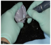
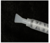
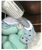
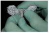
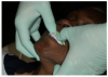
After the heavy-body material in the tray had set and the tray was removed, all exposed areas were relieved (Figure 3) and relined with additional heavy-body impression material. More adhesive was applied to the adjusted areas, and then light-body polyvinyl siloxane was applied over the heavy-body impression. Use of a ribbon-tip spatula (Figure 4) facilitates even distribution of this material and eliminates the need to use any metal spatula. Ideally, the thickness of the light-body wash material should be approximately 1 mm to 2 mm. It must cover the entire surface of the impression to capture the muscle details of the patient’s mouth.
With the wash material applied, the tray was seated firmly into the patient’s mouth. The patient was directed to relax her cheek muscles. One hand was then used to stretch and pull the muscles to obtain the best wash impression and correct border molding. The goal was to create the most harmonious borders possible so that when the denture was delivered, no overextensions or adjustments would be required.
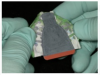
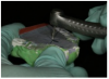
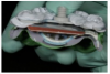
This master impression was removed from the patient’s mouth (Figure 5), and the next step was to separate the posterior portion of the tray. This was necessary to enable the patient to freely move in all lateral excursions and create the border movements required for the Gothic-arch tracing. (The trays are designed for easy separation.) In this case, a Bard-Parker® (Aspen Surgical) blade was used to slice through the impression material (Figure 6).
To articulate the upper denture to the patient’s partially edentulous mandible, the bite plate supplied with the Pala kit was covered with bite-registration material, and the center pin was attached (Figure 7). This pin is used to establish the vertical dimension of occlusion (VDO) and accomplish the Gothic-arch tracing. The tray was then placed in the patient’s mouth and held in position to prevent any slipping or tilting as the impression material set.
Because the patient in this case had some mandibular teeth, the bite impression was removed, and 3 mm of the vertical dimension screw was cut off (Figure 8). The bite tray and maxillary impression were repositioned in the patient’s mouth, and both were securely seated. The patient was instructed to gently close her mouth and refrain from biting too hard. The center pin was then adjusted until the patient’s lips were barely touching. Had the patient presented with a significant loss of VDO, as is common with severely worn denture prostheses, she would have been guided through phonetic exercises to assess the extent of the VDO loss. In this case, that was unnecessary.
The next step was to trace the CR at the vertical dimension by using the center pin as a Gothic arch tracer. Tracing material was positioned on the lower side of the maxillary tray (Figure 9), and with the impression and bite plate in position, the patient was instructed to move her jaw vertically and horizontally to trace the Gothic arch (Figure 10 and Figure 11).
The CR position was then marked by removing the tray and using a round diamond bur to create a small dimple at the point of the arrow (Figure 12). With this as a landmark, the rounded knob on the screw in the bite plate can consistently be positioned in the dimple in the upper tray no matter how much the jaw is manipulated. Large acrylic carbide drills should not be used for this task, as the loss of even a millimeter of VDO can compromise the fit of the denture.
With the maxillary impression and mandibular plate once again in position, the centric occlusion was confirmed. Polyvinyl bite registration material was then injected bilaterally and allowed to set in order to join the two pieces. They then were ready to be sent to the laboratory. No facebow was constructed. Instead, the necessary information was incorporated into the assembly shown in Figure 13.
Lip length is one additional measurement that is advisable for some patients (Figure 14). The length of the upper lip from the incisive papilla can be used by the software to help with placement of the maxillary central incisor edges in the phonetically and esthetically correct position.
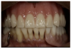
At the try-in appointment, the resin try-in denture confirmed good lip support and an esthetic incisor display, both when the patient was smiling and in repose. Even though no facebow was taken, the occlusal plane was not canted. Two small corrections were requested. The anatomic midline did not coincide precisely with the facial midline. Also because the denture was being created against a partially edentulous arch, the buccal cusp on the right first premolar needed to be extruded a bit to accommodate the plane of occlusion of the natural teeth. Both of these changes were incorporated into the final denture (Figure 15).
Discussion
Fabrication of a removable denture, as traditionally taught in dental school, involves a seemingly daunting number of steps. Typically, the first appointment is dedicated to making a preliminary impression of the arches. From this, a custom tray is created and used at the second appointment to make a master impression. For the next appointment, the laboratory fabricates and returns wax rims for creating a CR bite record. The upper wax rim is attached to a facebow to articulate the maxilla to the cranial base. Three appointments are, thus, required to get to a point at which the laboratory technician can start placing teeth. Later, the clinician must look forward to more appointments for delivering the denture to the patient, making adjustments, shortening the borders, and relieving sore spots.
In contrast, the digital denture process combines the primary and master impression-making. A Gothic-arch tracing is used to record the border movements of the mandible. The VDO is established, and the CR is taken with the tracing device. All this is compressed into the first office visit.
Conclusion
The digital denture process eliminates numerous steps from the process of fabricating removable dentures, while significantly improving the accuracy and fit of dentures. This technology offers the promise to reinvigorate the interest of dentists and laboratory technicians in providing patients with removable dentures at a time when the need for them is growing sharply.
References
1. Haden NK, Morr KE, Valachovic RW. Trends in allied dental education: an analysis of the past and a look to the future. J Dent Ed. 2001;61(5):480-495.
2. Zamanian K, Wong J. New technologies guide paradigm shifts in dental prosthetics industry. January 30, 2012. Dental Tribune website. http://www.dental-tribune.com/articles/business/usa/7335_new_technologies_guide_paradigm_shifts_in_dental_prosthetics_industries.html. Accessed February 2, 2015.
3. Christensen G, Yancey WR, Schoenbaum TR. The mounting challenges facing the lab industry and the effects on clinical practice. Dental Economics. 2013;103:36-39.
4. Douglass CW, Shih A, Ostry L. Will there be a need for complete dentures in the United States in 2020? J Prosthet Dent. 2002;87(1):5-8.
5. Holt LR. Digital dentures are a reality: a case study. Inside Dentistry. 2015;11(Suppl 1):2-5.
6. Beck CB, Bates JF, Basker RM, et al. A survey of the dissatisfied denture patient. Eur J Prosthodont Restor Dent. 1993;2(2):73-78.
7. Yoshizumi D. An evaluation of the factors pertinent to the success of a complete denture service. J Prosthet Dent. 1964;14(5):866-878.
8. Rudd RW, Rudd KD. A review of 243 errors possible during the fabrication of a removable partial denture: part 1. J Prosthet Dent. 2001;86(3):251-261.
9. Rekow ED. CAD/CAM in dentistry: a historical perspective and view of the future. J Can Dent Assoc. 1992;58(4):283, 287-288.
10. Duret F, Blouin JL, Duret B. CAD-CAM in dentistry. J Am Dent Assoc. 1988;117(6):715-720.
11. Duret F, et al. Realisation d’une couronne par ordinateur. Congres A.D.F., Paris; 25 November 1985.
12. Fuster-Torres MA, Albalat-Estela S, Alcaniz-Raya M, Penarrocha-Diago M. CAD/CAM dental systems in implant dentistry: update. Med Oral Patol Oral Cir Bucal. 2009;14(3):E141-E145.
13. Little D, McBride K. Implant-supported digital dentures: an accurate, efficient, and patient-friendly protocol. Inside Dentistry. 2015;11(Suppl 1):6-10.
14. el-Gheriani AS, Winstanley RB. The value of the Gothic arch tracing in the positioning of denture teeth. J Oral Rehabil. 1988;15(4):367-371.
15. Massad JJ, Connelly ME, Rudd KD, Cagna DR. Occlusal device for diagnostic evaluation of maxillomandibular relationships in edentulous patients: a clinical technique. J Prosthet Dent. 2004;91(6):586-590.
16. Massad JJ, Cagna DR. Immediate complete denture impressions: case report and modern clinical technique. Dent Today. 2008;27(3):58-65.
17. Massad JJ, Cagna DR. Vinyl polysiloxane impression material in removable prosthodontics. Part 1: edentulous impressions. Compend Contin Educ Dent. 2007;28(8):452-460.
18. Massad JJ, Cagna DR. Vinyl polysiloxane impression material in removable prosthodontics. Part 2: immediate denture and reline impressions. J Okla Dent Assoc. 2009;100(3):28-36.
19. Massad JJ, Cagna DR. Vinyl polysiloxane impression material in removable prosthodontics. Part 3: implant and external impressions. J Okla Dent Assoc. 2009;100(4):26-32.